
QSMP-13 Extra-Low-Cost Solder-down Module with STMicro STM32MP135C
Tiny QFN-Style System-on-Modules with 650MHz ARM Cortex-A7 processor
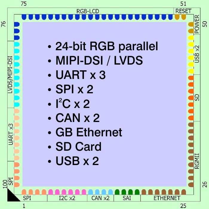
With a low unit price, QSMP-13 is a highly cost-effective 27mm x 27mm QFN Style solder-down system-on-module with STMicro’s  latest STM32MP135C ARM Cortex-A7 processor clocked at 650MHz, plus RAM, Flash memory and power management. QSMP is a sub family of modules based on STM32MP1 processors sitting within the Ka-Ro QS-Module pin-compatible family, which also includes SoMs based on STM32MP2, not to mention STM32MP157C modules with optional radio as well as NXP and Renesas processors. The module is square, with a height of 2.3mm. Its QFN-type pinout style features a 1mm pitch with 100 edge-located pads providing unparalleled miniaturisation, thermal efficiency and EMI minimisation – the base functions as both a ground pad and a thermal conductor. The module requires a single 3.3v supply.
The QSMP module’s STM32MP1 family processor allows us to offer both high performance (QSMP-15) via the STM32MP157A with dual 650MHz ARM Cortex-A7 core and GPU, and very low cost (QSMP-13) thanks to the STM32MP135C single core version. QSMP-13 features 256MB DDR3L RAM, 4GB eMMC Flash, and a good range of interfaces (see table). The module offers an extended temperature spec of -25C to +85C. Wide-ranging connectivity including CANbus, UART (x3), SPI (x2), I2C (x2), Audio, Gb Ethernet, SD, USB Host and Client and a parallel display.
QSMP-13 comes with a dedicated development system, equipped with Linux BSP.
To purchase a development kit simply follow the “Buy Online” link below.
 Download Datasheet and Pinout
| Resource | QSMP-13 | QSMP-15 | Detail |
|---|---|---|---|
| Processor | ST Micro STM32MP135C | ST Micro STM32MP157C | low cost or high performance |
| CPU | 1x ARM Cortex-A7 | 2x ARM Cortex-A7 | includes Neon SIMD / VFP |
| Processor Clock Max (MHz) | 650 | 650 | |
| Microcontroller | - | ARM Cortex-M4 | |
| RAM (MB) | 256 | 256 / 512 | DDR3L, see comparison tab below |
| Persistent Storage | 4GB | 4GB | |
| Floating Point | y | y | ARM Cortex-A7 Neon VFP |
| UART (RS232) | 5 | 3 | |
| Ethernet Gbe | 1 | 1 | |
| I2C Interface | 2 | 2 | |
| LCD Controller | 1 | 1 | 24bpp, 1366x768 |
| RGB display | y | y | |
| MIPI-DSI display | - | y | |
| Audio | 1 | 1 | SAI |
| SD card/SDIO (4-bit) | 1 | 1 | 4-wire, SD Card receptacle on baseboard |
| USB Host | 1 | 1 | Single "A" type socket on baseboard |
| USB Client/OTG | 1 | 1 | |
| SPI | 2 | 2 | |
| CAN | 2 | 2 | |
| Wi-Fi | - | option | Murata 2AE |
| Bluetooth | - | option | 5.2 |
| secure boot / crypto | y | y | |
| Temperature Range | -25C to +85C | -25C to +85C | -40C Wi-Fi/BT version |
| Dimensions | 27mm x 27mm | 27mm x 27mm | depth 2.3mm |
| Power Consumption | around 500mW | around 500mW | 15mW sleep |
| Linux | y | y | Yocto Scarthgap - LTS Kernel |
 The QSMP module has its own development kit called QSBASE1, and also works with the universal QSBASE4 kit which supports those QS modules with MIPI-DSI display interface. Both are supplied with Linux running out of the box.
QSBASE1
The QSBASE1 development kit is supplied with a QSMP-15 OR QSMP-13 module. There is an RGB connector for a touch screen (which can be optionally purchased), and connectors for SD Card, Gb Ethernet, USB Host. USB Power supply, and debug UART. All 100 module pins are brought to 0.1″ solder pads.
QSBASE4

QSBASE4 with Raspberry Pi Display
Most QS and QSX modules may use the QSBASE4 baseboard for development purposes. However, since the QSMP-1351 lacks a MIPI-DSI display interface, it is only supported by QSBASE4 for headless operation.
QSBASE4 is designed to accept socketed versions of all QS and QSX modules, and features:
- Gb Ethernet
- 2-port USB hub
- 2-Lane MIPI display connector – Raspberry Pi compatible
- 2-Lane MIPI camera connector
- Micro USB to UART bridge for debug
- USB type-C connector for client/power
- Expansion connector – RasPi power/I2C/SPI/UART compatible + CAN, SDIO
- JTAG ICE header

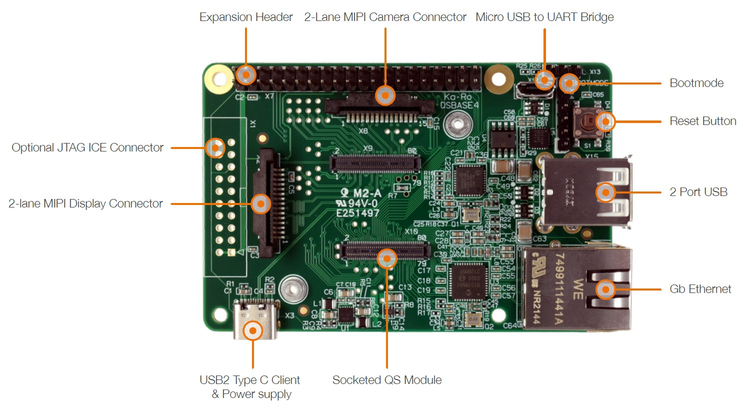
Special socketed versions of QS/QSX modules are connected via two 80-pin push-down connectors.
The QSBASE4 works with a standard Raspberry Pi 7″ touch display which is readily obtainable (we may also have stock). It is supplied complete with a USB-C cable for power and flashing, and a micro USB-B cable for debugging. The socketed modules are preflashed with a Linux image (contact support for details, and possible customisation).
The QSMP-13 module is available in the configuration below. See the comparison table below (also the feature table above) for options including QSMP-15.
ST32M1 comparison
| Processor | Part # | Module SKU | Cores | RAM | DevKit | CANbus | GPU+MIPI display | Temp Spec. |
|---|---|---|---|---|---|---|---|---|
| STM32MP135C | QSMP/135C/256S/4GF/E85 | QSMP-1351 | Single | 256MB | QSMP-13 QSBASE1 Evalkit | y | - | -25C to +85C |
| STM32MP157C | QSMP/157C/256S/4GF/E85 | QSMP-1530C | Dual | 256MB | QSMP-15 QSBASE1 Evalkit or QSBASE4 | y | y | -25C to +85C |
| STM32MP157C | QSMP/157C/512S/4GF/E85 | QSMP-1570 | Dual | 512MB | QSMP-15 QSBASE1 Evalkit or QSBASE4 | y | y | -25C to +85C |
QSMP-1351 – with STM32MP135C single-core processor, 256MB RAM, 4GB eMMC Flash, -25C to +85C industrial temp
Simply order the QSMP development system via our online shop, using the “Buy Online” link to the right, and it should be with you in a couple of days. We look forward to providing you with knowledgeable, professional support to create your product. If you have questions, please don’t hesitate to contact us by calling Direct Insight on +44 1295 768800 9am to 5.30pm UK time, emailing info at directinsight.co.uk, or by using the “Contact Us” form below.
Contact our experienced team with your detailed questions – we’ll be happy to help.
You can quickly access volume pricing information using the following link: Get Quote
Development kits and sample/spare modules are available from stock
QSBASE4 development kit recommended for QSMP-15 (requires QSMP157A socketed module)
QSBASE1 with QSMP-13 development kit recommended for QSMP-13
QFN-Style SoM Advantages
For larger volume applications, or where a tiny footprint is needed, Ka-Ro QFN solder-down modules fit the bill perfectly.
In addition they offer:
 Guaranteed lifetime is a key reason to choose us – we have been shipping modules for over two decades, and have a track record of offering several products for well over 10 years. Each module that we sell is guaranteed to be available, in small or large quantities for at least 12 years from launch. This is a minimum, with expected lifetimes of 15 years where possible. Direct Insight has a unique track-record in maintaining partnership with our customers for the long-term, supporting you throughout the product life-cycle.
 Because the TRITON-TX modules are manufactured in a high-quality small-batch production facility within the EU, there are never problems with manufacturing standards or with supply. If you order 100 modules and we don’t have them in stock, we will make them. Often, cheap modules are produced in large batches by volume-oriented contract manufacturers in the Far East, and once they are gone, they are gone.
 Our BSPs whether for Linux, or other supported OS are complete, and are designed so that you can use them without further development or modification. One of the key advantages of the system-on-module approach is rapid time-to-market, and requires a reliable, production-ready BSP, and a ready-to-roll compatible tools setup. For Linux, we supply a pre-configured VM SDK so that the kit and tools are ready to use out of the box.
 Further to our longevity guarantee, additional security is provided by the pin-compatible nature of theQS-Module ranges, which means that suitable baseboard designs can take all the modules from this family, from the low-end low-cost QSMP, to the i.MX8 based QS8M and allows older modules to be replaced by the latest designs, with new features, better price-performance, and renewed longevity.
 Striving for the best technical support provision to our customers is what makes Direct Insight stand out. Using a system-on-module is all about achieving a quicker, smoother route to project completion. We have supported our customers in many hundreds of system-on-module projects over the last 15 years, and are uniquely placed to assist you.
The STM32MP157C processor features secure boot capability which potentially allows the user to secure the device against code modification, while preserving the ability to update. This is achieved by programming public keys into the device, against which the private-key signed image and data are validated. We offer secure boot programming during manufacture to enable customers to easily secure their device.
